Author: Kaleb Sabo

  • The Latest Build: An IPhone Quadpod Stand

    The Latest Build: An IPhone Quadpod Stand

    Hello! Today’s Print Review is a custom IPhone Quadpod Stand for recording or taking pictures. If this is your first time reading, I will be going over a 3D print build from scratch to completion all within the FreeCAD environment. There are few new techniques in this one that I found extremely useful and hope you do too!

    Welcome to SzaberDesign

    Let’s start off with one of the most important things to get right, and that is defining…

    The Build

    It cannot be overstated how important it is to define the build and stick with it. No breaking scope, no extras and no excuses. For this project, we need to accomplish a few simple needs for a phone stand:

    • Grip: Able to securely hold a phone
    • Height: Needs to reach 1.5 meters (about 5 feet) into the air, around standard head height
    • Balance: Cannot tip over easily

    These requirements seem easy on paper, but as you keep reading you’ll see how hard it was to understand exactly what it takes to engineer them together.

    Grip

    Developing a clip in FreeCAD can be fairly straight forward process: a bunch of rectangles, a couple pads and your done. BUT, we are dealing with an expensive phone and need to make sure it will stay in place and in one piece.
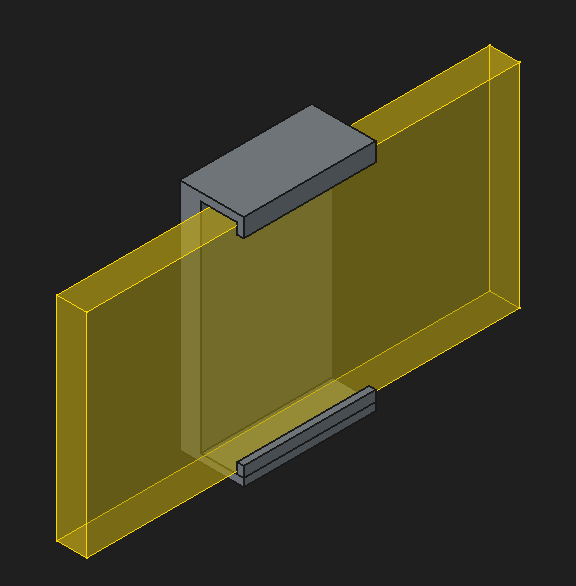
    The Subshape Binder Tool is a lifesaver. It is a reusable copy and reference part. We will be using it to get an accurate picture of the size and shape of a phone so that the clip is perfectly squeezing the phone exactly like we want.

    Highly recommend this video FreeCAD 1.0 | Shape Binders by MangoJelly Solutions to learn all about it.

    In fact, I’d recommend this entire video series to anyone that is interested in learning about FreeCAD.

    Height

    We have a working grip for the phone, so now we need the mechanism to raise the phone into the sky. But before we start building the 1.5 meter long pole, there is a single constraint that changes the entire dynamic of the build.

    • The size of the printer bed

    Currently, I run a Bambu Lab A1, which has a bed dimension of 256mm*256mm*256mm. Not 1.5 meters. So how do we overcome? Stacking.

    Using a ‘shadowbox’ method, we can mate two of the small poles together and repeat on each end, creating the stacking process to inevitably reach the 1.5 meters we need.

    We have a pole and a gripper, and no way to connect them together. So lets combine one of these shafts and embed a seat for the gripper.

    There is a problem here, though. The gripper will sit perfectly into the part, but there is no staying power. One push and the phone falls. So, lets dive into heat-set inserts.

    A few considerations to set up these heat-set inserts

    • Screw, shank and heat-set insert sizes
      • Were trying to go through the back of the connector into the gripper.

    After doing the calculations and carefully working with a solder gun, we can press the inserts in.
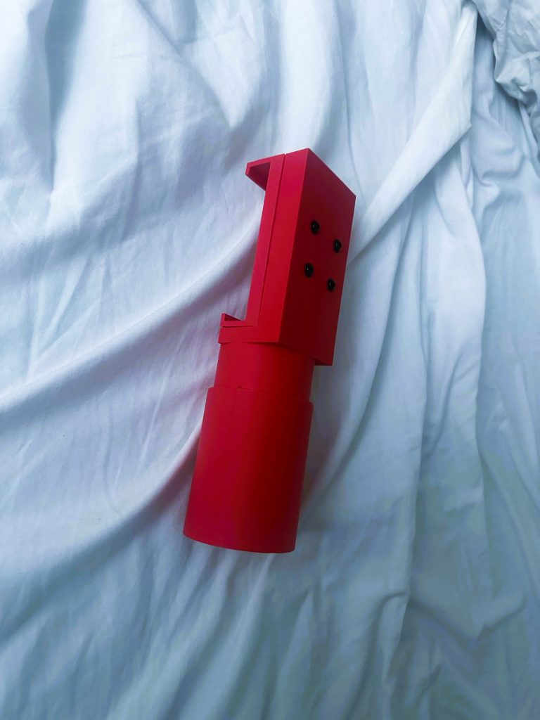
    And just like that, end up with a secure foundation for our phone.

    Quick Review:

    • We have the Height
      • Using the ‘shadowbox’ method and stacking our pieces to reach the 1.5 meter goal
    • We have the Grip
      • The phone sits securely at the top

    We could stop here and still have a phone stand using one of the poles as the base, but the slightest breeze or awkward placement will send it tipping over. We need…

    Balance

    A brief deep dive into a few balance mechanics (which I highly recommend checking out)

    • Tipping Force vs. Restoring Force
    • Lever Arm and Pivot Point
    • Torque
    • Base of support

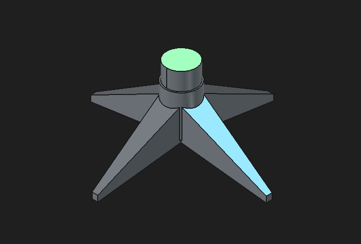
    By applying these principles, come up with, in my opinion the coolest part.

    Like our previous gripper/pole combo, we add mirrored legs to a copy of one of the poles and we end up with a dramatically increased Base of Support and a highly stable stand.

    And with this, the build is complete!

    Lessons Learned:

    • Scope (Good)
      • The discipline to not increase the scope during the project, really kept the development time to a minimum
    • Clones (Bad)
      • In FreeCAD I failed to realize the power of clones, I manually manipulated the master copy of the poles to make the gripper combo and the stand. A lot of wasted effort here that cloning could have solved.
    • Dimensions (Good)
      • Keeping up with the master spreadsheet for all the dimensions really ensured that the final product was done in one shot rather than going back with continuous micro fixes.

    Thank you for reading, if you have a question about anything or a suggestion for a better method, drop it in the comments below!

    Side Note:

    A video showcasing the effectiveness of the IPhone Quadpod along with a massive announcement on the launch of a new YouTube channel showcasing some heavier engineering and robotics projects is coming soon! Stay tuned!
  • Examine the Build: a 3D Printed Business Card

    Examine the Build: a 3D Printed Business Card

    What better way to launch a 3D printing portfolio than with a business card that is the portfolio?

    Welcome to SzaberDesign

    To kick things off, I’m starting a new series: Print Review. I’ll be breaking down the exact mechanics, failures, and fixes behind these designs. If you’ve tackled similar builds, drop your solutions in the comments.

    For now, let’s break down the two immediate design hurdles for V1:

    The Logo: How to get a simple image onto a card

    Two-Tone Leveling: Two colors, The background and foreground


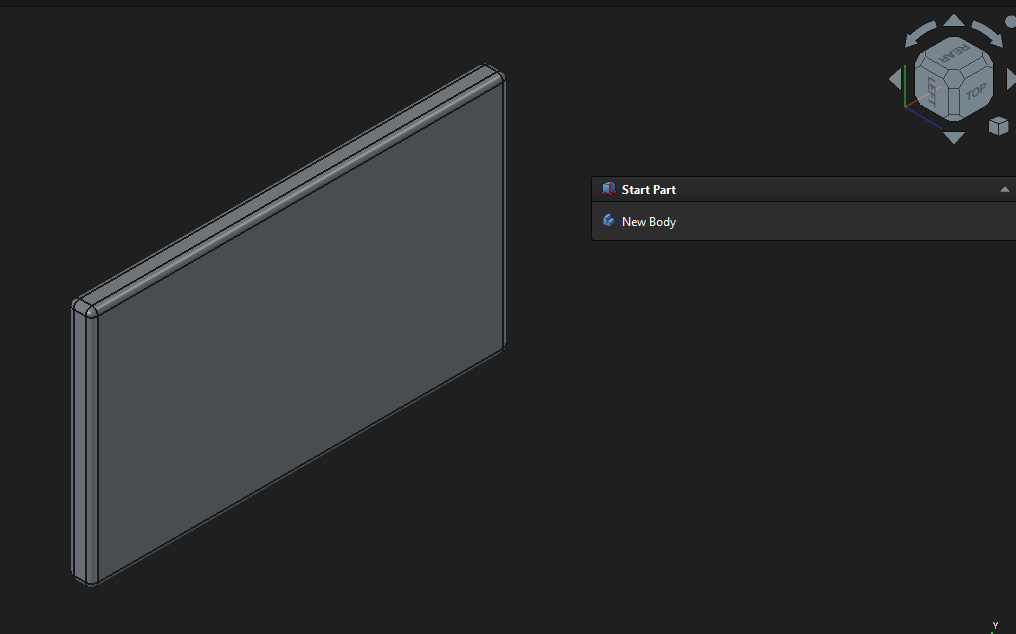
    Beginning in my favorite open-source Computer-Aided-Design (CAD) software, FreeCAD, the project starts with a rectangle, an extrusion/pad, throw in a few fillets (curves) and bang.

    A neat, blank business card ready for information.

    The Logo

    One of my favorite parts to learn in this build.

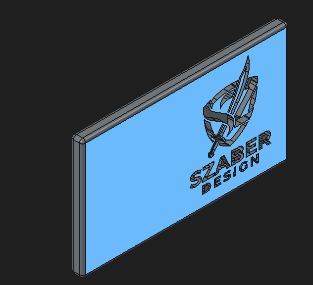
    Objective: Get an image into FreeCAD and create a dynamic hole or pocket into the model.

    Here’s how I did it: Start with an image, preferably something with clear lines (like a logo), and upload it to a vector-graphics editor. Keeping with the open-source theme, I recommend Inkscape.

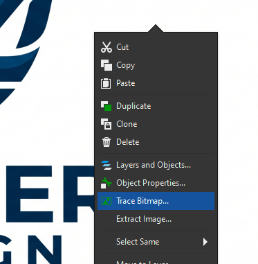
    With the uploaded picture in Inkscape, right-click and select Trace Bitmap.

    Inside the new window, click “Apply”. And finally, Export as [.svg] (this is important!).

    Now you should be ready to upload in FreeCAD where you will get a nice clean cutout of the image. (a few more steps here but let me know if you would like me to explain it)

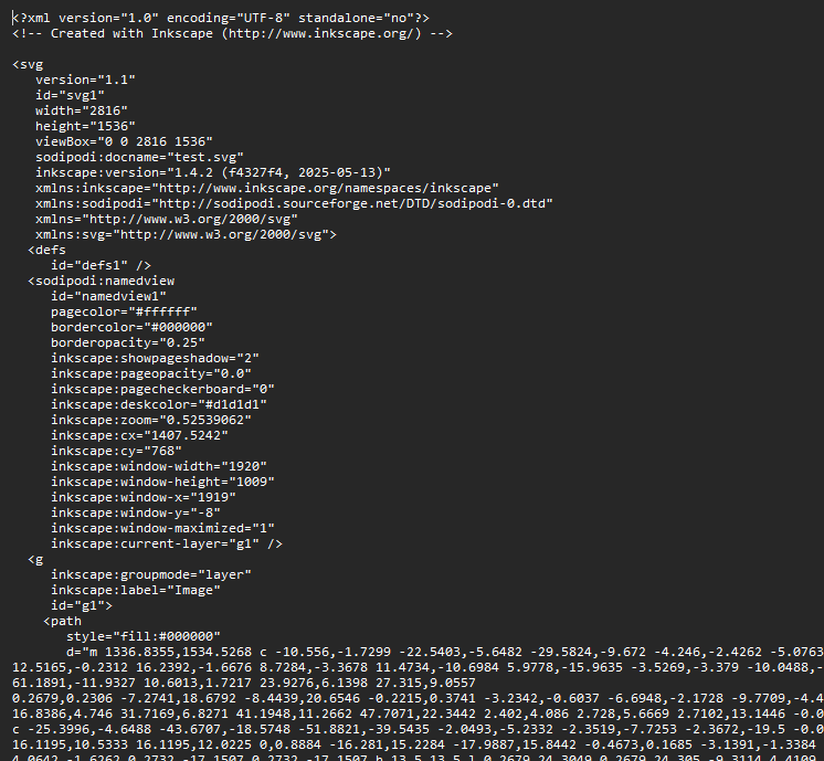
    SIDE NOTE: The [.svg] is so important for this, it essentially takes your image and turns it into a mathematical text document. When you get some time check it out, right click and open a [.svg] image inside notepad and you will get a bunch of numbers. Its a numerical representation of the image, pretty cool!

    Two-Tone Leveling

    After cutting the logo and little design flavorings. We can begin thinking about the color for the card. In this case, black and white.

    A surprisingly easy way to implement this is to change out the filament halfway through a print, which you can do through the slicing software for your 3D printer. My go-to software right now, which is also open-source, is Bambu Studio from Bambu Labs.

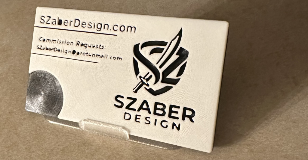
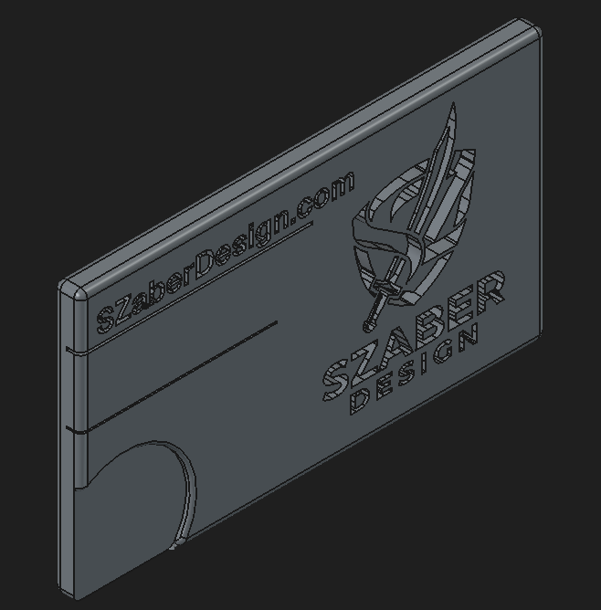
    SzaberDesign Business Card V1

    A solid first build for a business card!

    Lessons Learned

    One of the biggest issues with the card is the left-hand lettering and how unclear it is. Several factors contributed to this.

    • Size: The card went from 100mm to 200mm along with managing the width of the email address all during slicing, it should never be edited so much during this step ideally.
    • Placement: I never placed a snapping grid for the letters inside the CAD software, alignment was a matter of how close it looked to the eye (see how the ‘C’ in Commission and ‘S’ in the email are off)
    • Nozzle: a 0.4mm nozzle required the lettering to be big enough so that it is legible and strong.
    • Spreadsheets: The “spreadsheet discipline” only the card itself had dimensions not the letters etc. Not very professional (although all my prints now have drastically increased in this regard)

    Let me know in the comments if you have made anything similar before! Thanks for reading!

  • First Post with the First Print

    First Post with the First Print

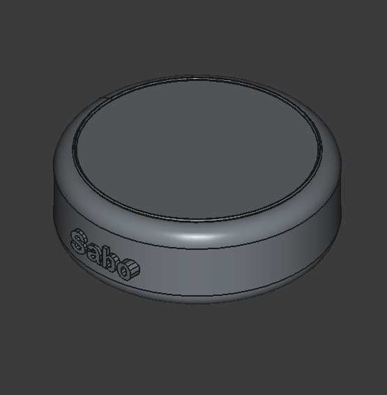
    Hello! I’m Kaleb. Welcome to the site. Before we dive in, you might be wondering about the image above. That’s one of my very first solo 3D prints, born out of a marathon sequence of FreeCAD tutorials. While it’s a simple piece, it stands as a great reminder of where I started and all the ambitious builds that are on the way.

    What I Do

    I am a Maker driven by the need to build. Rather than sticking to a single subject, my projects bounce across various disciplines. This constant experimentation has helped me develop unique techniques for 3D printing and creating custom gadgets that break the mold.

    What You’ll Find Here

    This site is a living log of my work. As you explore, you will find:

    • Active Projects: Behind-the-scenes looks at the mechanical builds and gadgets I am currently developing.
    • Downloadable Assets: Free 3D print files ready for you to download, modify, and use in your own projects.

    Feel free to use the files as you wish, and definitely let me know what you think!